Today (NST)
Monday, Jun 16, 2025
Smart Search
Please post in your Technical Queries, Comments & Suggestions to Contact us......
Advertisement

For Advertisement
|
|
| Subscribe to BREINS Sci-Tech |
| Visit this group |

Seismic Retrofitting
Retrofitting of Load Bearing Masonry Structures
Load Resisting Mechanism of Load Bearing Wall Structures
Methods to Strengthen Load Bearing Wall Structures
Special Considerations for Earthquake Safety
Load Resisting Mechanism of Load Bearing Wall Structures
Load bearing brick wall structures are basically a box type structure that resist earthquake loading by integral action of the walls and its cross walls (walls along perpendicular directions). During an earthquake shaking, brickwalls in a structure are subjected to the forces: both in-plane and out-plane directions of the wall panel.
In such, brick wall panels should be strong enough to resist earthquake loads both in in-plane loading and out-of plane loading. In-plane loading is basically resisted by shear strength of brick masonry; whereas, out-of plane is resisted by flexural action of the wall panel. Shear strength and flexural strength of brick masonry play a significant role in Load Bearing Brick Masonry Structures.
Configuration of these walls plays a great role in the development of stresses in brick masonry. Load bearing brick wall structures with large window /door openings and with low numbers of cross walls are among the most vulnerable ones. With increase in overall building height of structure above three storeys, it becomes even more vulnerable in terms of an earthquake loading. The brick wall panel with length exceeding its height without any cross walls in between is not desirable one. Such walls are dangerous in out-of plane loading.
Integral action of the wall and its cross walls at the intermediate locations and also at the corners is of primary importance. For this, joints between these two perpendicular walls should be strong enough to resist the earthquake induced forces. Such joints are the major locations that need to be strengthened from seismic point of view.
Methods to Strengthen Load Bearing Wall Structures
Load Bearing Masonry building structures could be strengthened by following simple steps.
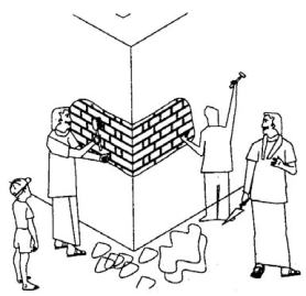
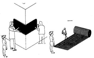
Stengthening of joints and wall panels could be done by fixing of steel wire mesh at the wall corners/walls through nails or connector-links drilled through the wall thickness (Fig-2,3 & 4). The mesh is covered by rich mix of cement-sand mortar in the ratio of (1:3). To achieve good results, the following step-wise procedure is to be followed;
> Cut the existing plaster at the edge by a mechanical cutter for neatness, and remove the plaster (Fig-2).
> Rake the exposed joints to a depth of 20 mm. Clean the joints with water jet.
> Apply neat cement slurry and plaster the wall with 1:3 cement – coarse sand mix by filling all raked joints fully and covering the wall with a thickness of 15mm. Make the surface rough for better bond with the second layer of plaster.
> Fix the mesh to the plastered surface through 15 cm long nails driven into the wall at a spacing of 45 cm tying the mesh to the nails by binding wire (Fig-3).
> Now apply the second layer of plaster with a thickness of 15 mm above the mesh. Good bonding will be achieved with the first layer of plaster and mesh if neat cement slurry is applied by a brush to the wall and the mesh just in advance of the second layer of plaster.

Fig-2 (Removal of plaster and raking of joints)

Fig-3 (Laying of steel wire mesh at building corners)
If the wall length is too large with respect to its height, the stresses generated on such wall panels could be higher during out-of plane bending. So such large span could be broken at certain locations by providing additional cross walls or by means of steel channel jacketing.

Fig-4 (Laying of Steel Wire Mesh at Brick Masonry Walls in one of its retro-projects by BREINS Structural Care. Pic Courtesy : Building Research Institute (P) Ltd., Nepal)
Special Considerations for Earthquake Safety
During earthquakes, acceleration would be higher at the upper storeys of the load bearing wall structured buildings. Due to this, wall panels at the top level are highly vulnerable; both in out-of plane and in-plane.
Also, at the upper floors, the compressive stress in brick-masonry due to dead load from upper storeys would be minimum than in lower storeys; hence lower shear strength of such masonry walls at upper storeys. In earthquakes, upper storey failures are more likely to occur in a load bearing wall system; so retrofitting measures shall be carried out in upper floors in much more detail manner.
Masonry walls with large window/door openings, without lintel/sill bands are the weaker ones. Stress concentrations at such window/door opening's corners may take place and failure is more likely to initiate through these locations. Also, out-of-plane loading can severely damage and even cause collapse due to lack of rigidity in such walls. To strengthen such wall panels, door/window openings could be replaced by the solid walls or steel bands, channels could be provided from both sides of the wall running throughout the opening's periphery.
Likewise, horizontal bands of steel wire mesh at the sill and lintel levels could be provided from both sides depending upon the wall’s thickness. These actions would significantly enhance performance of brick masonry walls and overall structure's performance too. Besides, in masonry structures, masonry walls should also be checked for the development of in-plane shear stresses that could occur during an in-plane earthquake loading and suitable jacketing measures shall be employed to strengthen it as per the requirement.